Architecting Processes for Verified Design Inputs (Demo)
The FDA identifies defining design inputs as the most critical design control activity. Yet organizations rarely verify the adequacy of those inputs before generating design outputs against them. When design inputs are not rigorously verified early, the risk of developing a product that fails to meet performance or quality expectations increases significantly. Deficiencies often remain hidden until formal design verification and validation, when correction becomes costly. Organizations that implement structured, early verification of design inputs reduce rework, mitigate business risk, and improve the efficiency of device commercialization.
Design inputs must be verified through structured analysis. Regulatory expectations are typically met by demonstrating traceability from user needs to design inputs in early development and from hazardous situations to design inputs as risk management matures. However, for complex systems, additional rigor is required early in development, as incomplete, ambiguous, or conflicting inputs significantly increase downstream cost and rework.
Figure 1 illustrates an alternative traceability model that can be used to evaluate different approaches for verifying design inputs. Regardless of the model selected, maintaining clear traceability from the business case to design inputs is essential to ensuring technical alignment and commercial viability.
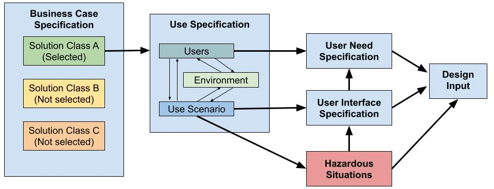
Figure 1 – Design Input Activity Network Diagram
Whether design inputs can be meaningfully verified in early development is often debated. Traditional medical device practice has long associated verification with inspection, testing, analysis, or demonstration performed on finished products. While design verification is widely discussed, regulations define verification itself — not “design verification” as a separate concept.
This distinction is critical. Verification is confirmation, supported by objective evidence, that specified requirements have been fulfilled. When applied consistently, this principle extends beyond final product testing to every development activity, including the definition of design inputs. Expanding verification in this way reduces ambiguity, strengthens decision-making, and embeds rigor early in the system.
The following sections outline analytical approaches for verifying each specification identified in Figure 1. These examples demonstrate how design inputs can be rigorously verified through analysis. Organizations should tailor the approaches to align with their system complexity, regulatory environment, and development model.
The model illustrated in Figure 1 organizes product specifications into a structured framework. These specifications represent the requirements that design outputs must satisfy and embody key product decisions made during development. While purely subjective review is insufficient, complete objectivity is rarely achievable; therefore, organizations must rely on structured decision-making methods.
Table 1 outlines validated analytical processes for evaluating each specification. Together, these processes provide consistent, evidence-based confirmation that intended decisions and outcomes are achieved.
| Specification / Analysis | Decisions & Outcomes |
| Business Case Specification (BCS) / Business Case Analysis (BCA) | The business defines the problem or opportunity being addressed by a given portfolio or program. Groupings of related products that share common characteristics, functionalities, or target problems are analyzed. An appropriate solution class for the problem or opportunity is selected. |
| Use Specification (US) / BCS-US Traceability Analysis | The solution space is analyzed based on the selected solution class and business case considerations. The intended users, environment, and use scenarios are defined. Understanding of how users are intended to interact with the product and supporting systems, if applicable, are validated using models. |
| User Interface Specifications (UIS) / Use Failure Modes & Effects Analysis (uFMEA) | Models defining user interactions are analyzed to determine testable requirements related to the usage of the product. Characteristics of the device related to its safe and effective use are defined. |
| User Needs Specification (UNS) / US-UIS-UNS Traceability Analysis | Areas where user concerns may be relevant are identified based on the usage and user interfaces. Without regard of the design of the product, user needs are defined to qualify the solution in terms that address the user’s concerns. The needs of the user are expressed as itemized specifications and whether they sufficiently address the intended user interactions is checked. |
| Design Inputs (DI) / UN-UIS-DI Traceability & Hazard Analysis (HA) | The stakeholder’s (e.g. shareholders, management, and users) expectations for performance and quality are expressed as itemized specifications. Design inputs’ ability to address medical device risks and to implement the desired user interface characteristics is checked. Agreement is obtained that the stakeholder’s needs and expectations for the product are adequately defined. |
Table 1 – Output Specification from the Design Input Activity
Business case specifications aim to define characteristics of the solution class that address the problem or opportunity selected. Alternative terminologies include business requirements, market needs and customer requirements to name a few. These specifications must conform to and relate to market research. Organizations often tend to accept business cases based on the described potential of the proposed solutions, but it is prudent of organizations to check if they selected the “right” solution. This very well may be the first opportunity to make the “wrong” product.
The purpose of the business case analysis is to verify that the selection of and the constraints around the solution class selected are adequately justified. The people making decisions must consider all the costs, risks and benefits in developing the solution class selected. The criteria used to select the right solution from alternatives, and the results of the evaluation should be documented. This helps ensure decisions are adequately reviewed when they are approved and can help evaluate change proposals down the line. An approach to performing business case analysis is illustrated in Figure 2.
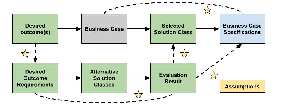
Figure 2 – Business Case Analysis Workflow
Solution classes should be selected using a combination of financial and non-financial considerations. Financial considerations include the potential profitability of approaching a problem or opportunity in a certain way. Non-financial considerations may outweigh simple profitability estimates and may include morale, maintainability, supportability or customer satisfaction. These considerations can provide a basis for requirements by which the alternative solutions can be selected and evaluated. The description of each workflow element from Figure 2 is presented in Table 2. Once this or an analogous approach is followed traceability between the problem or opportunity being addressed and the preferred solution class is established.
| Workflow Element | Description |
| Desired Outcome(s) | Define the mission, business, or operational problem or opportunity that must be addressed by the solution. |
| Desired Outcome Requirements | Itemize the key parameters and critical success criteria based on the desired outcome(s). |
| Alternative Solution Classes | Identify all potential solution classes that may address the requirements of this business case. |
| Evaluation Results | Define how different alternatives were evaluated for the purposes of selecting an alternative that addresses the desired outcome. Evaluate the alignment between desired outcome requirements and alternative solution classes. |
| Selected Solution Class | Justify the selection of the solution class as opposed to the alternatives that were evaluated. |
| Business Case Specifications | Itemize characteristics of the solution class in terms of how the business aims to achieve the desired outcome. |
| Assumptions | State any assumptions made when: Defining requirements for the desired outcome. Evaluating alternative solution classes. Selecting solution classes based on evaluation results. Imposing information from the business case to the business case specifications. Carrying over why the solution class was selected into the business case specifications. |
Table 2 – Business Case Analysis Elements
Use specifications serve as the foundation for the usability engineering efforts and risk assessments. They outline the device’s intended user profile(s), use environment(s), use scenarios, and operating principles. The use specification must conform to business case specifications and user’s expectations. Assumptions made about financial and non-financial considerations must be carried over through the use specification to maintain consistency. This can be verified by analyzing the traceability between business case specifications & use specifications (business-use traceability analysis).
BSC-US traceability analysis is performed because how the business aims to achieve desired outcomes must align with the user interactions defined at this stage. Traceability analysis identified at this stage can help:
- Ensure completeness of the defined use scenarios in the context of the business case.
- Evaluate whether defined use scenarios are complete for the specified user groups.
- Scope use scenarios as an interaction by a user group in an environment with an intended result from the medical device(s).
- Evaluate the defined user groups in the context of the environments and scenarios.
- Evaluate the defined use environments in the context of the users and scenarios.
Comparison between Figure 3 and Figure 4 illustrates how analyzing traceability between elements of the business case and use can be used to incomplete or inconsistent use specifications. If the output of these specifications is used to define user interface specifications and user needs specifications, then inadequately defining the use specification may result in design efforts yielding the “wrong product”. Further, the use specification provides the basis for design validation, so inadequate use specifications may also lead to poorly designed usability studies (acceptance of the “wrong” product). The risks associated with inadequate use specifications are significant because they may result in rejection of the product(s) by the end-users and/or stakeholders after the total design effort.
Devising the use specification is a critical activity from a business standpoint. In addition to performing traceability analysis and evaluating the results, it may be helpful to model the interactions between the product(s) and users. This can be accomplished using sequence diagrams. Assumptions about the defined user interactions derived from the models can and should be validated early-on with stakeholders, especially the intended users. These formative usability studies help understand whether prospective users are properly identified and check whether the solution is being designed to be used in ways and where they expect.
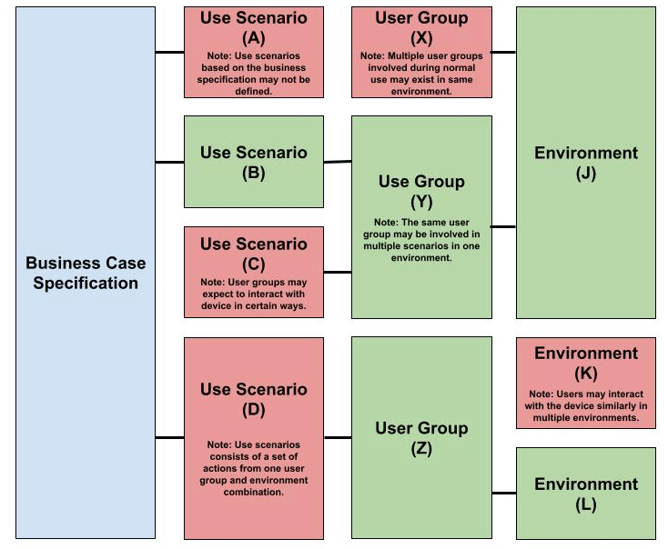
Figure 3 – Business-Use Traceability Analysis Elements with Errors
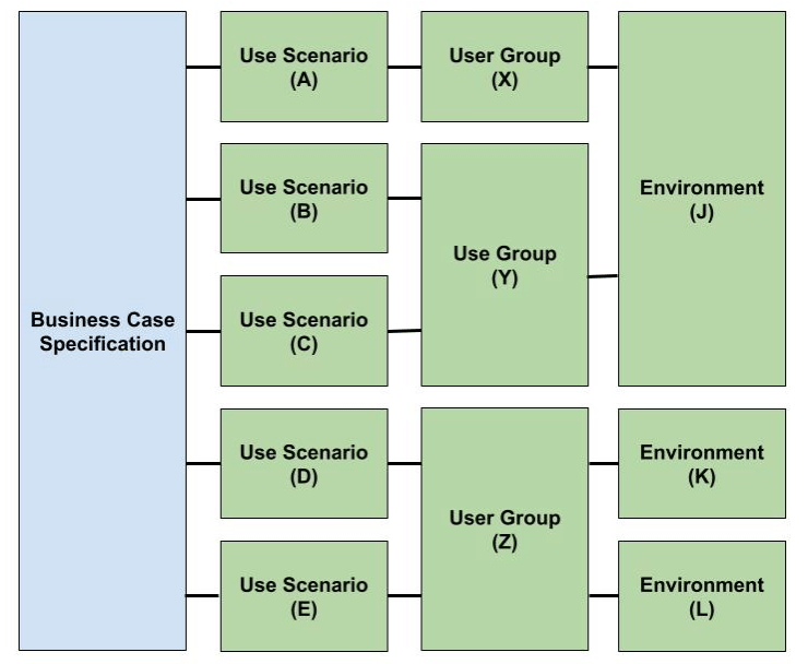
Figure 4 – Business-Use Traceability Analysis Elements without Errors
User interface (UI) specifications provide a basis for implementing the user interface and define requirements for testing with prospective users. UI specifications may be used to document items like color, size, etc., that are related to the usage of the device, but herein they are used to define what the user must accomplish in the relation of each use scenario. The user must be capable of operating the device without failures when design failures are not present. Hence, user interface specifications must address use-related failure modes, and these can be catalogued using Failure Modes & Effects Analysis (FMEA).
Use Failure Modes & Effects Analysis (FMEA) is the specific instance of FMEA activities where the elements being analyzed are use scenarios (on this page). It starts with all the ways that use scenario fails meet its success criteria. It may not be necessary to define each potential use error at this stage because these can be assessed along with hazardous situations as described in Figure 1. Next, the potential failure causes and effects are defined. The risk associated with the failure effects can be used to prioritize UI specifications. UI specifications are set to control the associated risks due to failure of the use scenarios. An approach for performing use FMEA to derive UI specifications Is illustrated in Figure 5.
At early stages preliminary understanding of how the user interacts with the device should be sufficient to generate an initial revision of the use FMEA. Use scenarios may not be fully carried through to other system elements, but the intended result in the medical device should be known for each. The facilitator can rely on groups brainstorming what ways the use scenario does not arrive to the intended result, what would cause this based on the solution class, and what would be the effect. Similarly, for each “failure cause”, they can ask if this were to occur, would there be other ways in which the use scenarios can fail? Lastly, for each “failure effect”, they can ask is there any other cause that can lead to this effect? The assessment yields a preliminary set of UI specifications that can be refined throughout the development process.
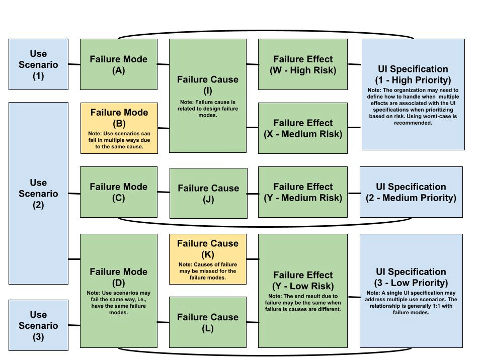
Figure 5 – Use Failure Modes & Effects Analysis (FMEA) Workflow
A universally accepted definition of user needs does not exist; however, manufacturers must provide objective evidence that device specifications conform to them. User needs are best understood as the acceptance criteria defined by users and patients. During design validation, manufacturers must demonstrate that these needs were properly identified and that the device meets or exceeds them. Verifying user needs early in development strengthens the foundation for design inputs and reduces the likelihood of disruptive changes later in the lifecycle.
Demonstrating completeness of user needs identification can be achieved by verifying traceability between use specifications (USs), user interface specifications (UISs) and user needs specifications (UNSs). An approach to performing US-UIS-UNS traceability analysis is shown in Figure 6. This approach is expected to offer the following benefits:
- Helps identify whether users have different needs when interacting with the device(s) in similar ways.
- Helps identify whether the same users have different needs when interacting with the device(s) in similar ways in different environments.
- Helps identify whether groups of users have the same needs when interacting with the device(s) in the same way.
Most importantly, it is expected that when traceability analysis is performed for user needs that previously developed user needs become more refined. Organizations tend to specify user needs that are vague like users need a device that is easy to use. This can be considered a valid approach, but it is not very helpful when devising validation studies or defining design inputs. The question here becomes given a specific combination of a goal, environment and interactions, what would describe the user’s need in that moment?
Lastly, user needs that are further refined this or analogous approaches are easier to confirm with pre-market research. Minimal research is needed to confirm user needs that are written to be non-controversial and open-ended. They are less likely to be incorrect, but they are not very informative. Specifying that for a given environment and set of interactions that the user needs something specific like alerts, ability to troubleshoot, etc., makes it easier to achieve confirmation of these needs during usability studies.
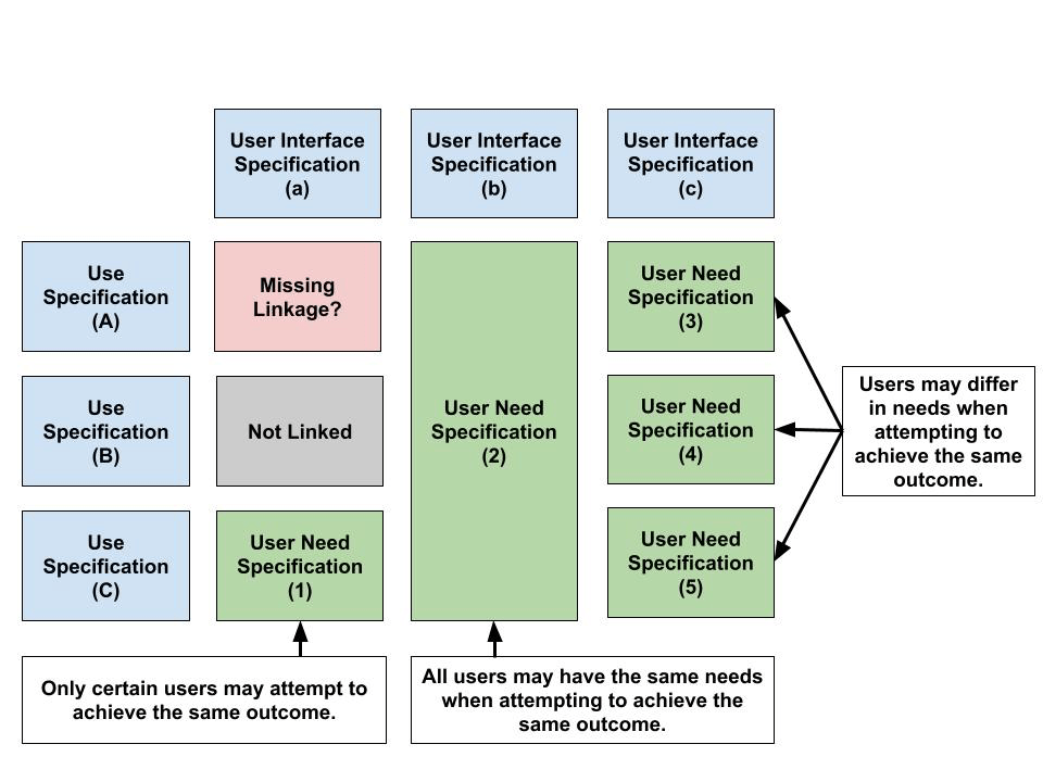
Figure 6 – US-UIS-UN Traceability Analysis Workflow
Design inputs (DIs) form the technical foundation of device design. They define the physical and performance requirements that design outputs must satisfy and establish the criteria against which those outputs are verified. Design inputs must address the device’s intended use, including the needs of users and patients. Approval of design inputs marks the formal initiation of design and development activities, making this milestone one of the most critical decision points in the lifecycle. The analytical rigor applied in previous sections is intended to increase the likelihood that the initial set of design inputs is complete, coherent, and aligned.
Within the defined model, design inputs serve a dual purpose: they guide the development of design outputs and anchor the verification architecture of the system.
Firstly, design inputs are used to define how the user interface is implemented in the design of the product. When user interface specifications are used to define what the user must be capable of accomplishing, then design inputs answer how the device addresses these events. These design input requirements are further refined using user needs specifications. A workflow to implement the user interface using design inputs is illustrated in Figure 7 using UN-UIS-DI traceability analysis. In this analysis, user need specifications or user interface specifications must be sufficiently addressed using design inputs. Additional or alternative design inputs may be defined because of this process.
Secondly, design inputs are used to define physical or performance product requirements that are verified for the purposes of risk control. Design inputs must contain the outputs of risk management following ISO 14971, which relies primarily on hazard analysis (HA). Implementing design inputs as risk mitigations for hazardous situations should yield acceptable (estimated) risks following the company’s risk management plan. At this stage, a primary resource to identify hazardous situations is the use FMEA conducted because use failure modes are sources of risk. The bottom-up approach following use FMEA should marry back up with the top-down approach defined using hazard analysis as illustrated in Figure 8. All available information like adverse events databases for the solution class when identifying hazardous situations, so it may be necessary to refine failure modes using the hazard analysis. Conducting this preliminary hazard analysis helps verify that the design inputs defined sufficiently mitigate medical device safety risks.
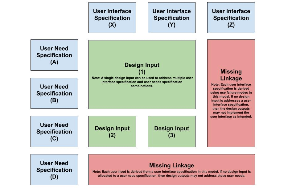
Figure 7 – User-Driven Design Input Definition Workflow
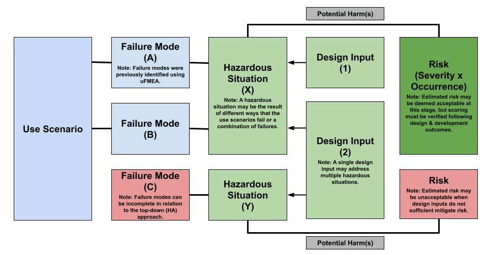
Figure 8 – HA-Driven Design Input Definition Workflow
To provide an example on developers can implement this process, a small-scale example of a manufacturer developing a simple in-vitro Diagnostic (IVD) device is explored. The example is illustrated in Figure 9. The example is not intended to portray a complete example and instead only aims to demonstrate how the different elements within the model can be linked. In this example, the design input is confirmed via traceability between business, risk management and usability outputs.
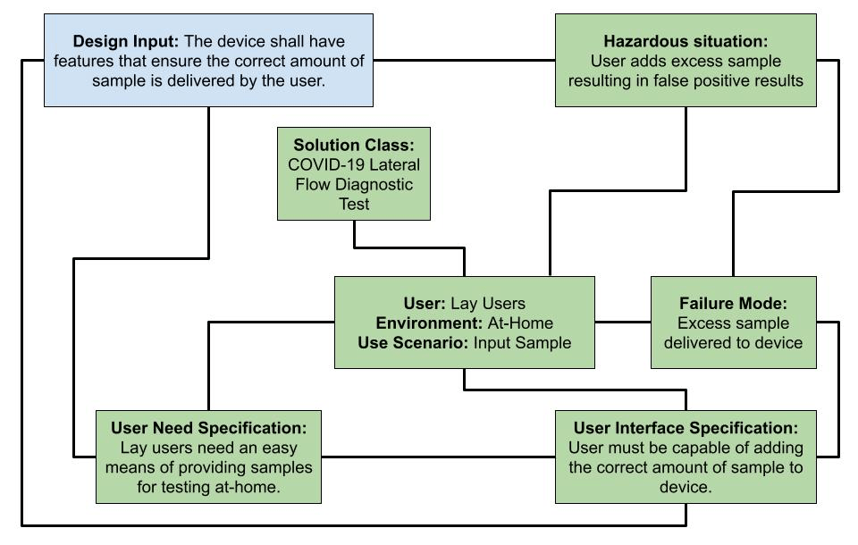
Figure 9 – Design Input Outcome, Working Example
